
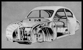
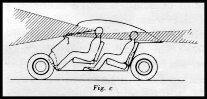
 The body, which serves simultaneously as the framework, may be regarded as a closed shell which combines the tasks of supporting the passengers and protecting them against adverse atmospheric conditions and shocks (in case of accidents) whilst at the same time it provides the necessary stiffening and load-supporting connection between the four wheels.
From the p6int of view of strength the shell is somewhat incomplete on account of the openings for the glass windows and doors which carry no load. The door openings and windows present the most serious problems. With the reinforcements that have been introduced, however, the body functions approximately as a rigid shell in the manner described below.
The rear window is surrounded by a frame fixed on the inside by spot-welding so that it causes no appreciable weakening of the structure. The rear sidewindows are substantially triangular in shape and, in consequence of the stiffening frames employed, may be regarded as entirely rigid.
It will be seen, therefore, that we may consider the shell as a continuous unit from the back up to the rear edge of the doors. This part of the body resembles an egg shell of which a large part of one end has been removed. Consequently, the edge of the shell can be easily deformed, but by inserting a bulkhead or bottom a short distanceinside the shell a great stiffening effect is produced. In the body this bulkhead consists of the sloping wall which serves simultaneously as the back support for the rear seats. (It is true that there is a large aperture in the wall to allow access to the luggage compartment,but owing to the wide surface of the plates on three sides this wall functions as a solid wall.)
That part of the body described hitherto represents a rear closed portion in which the roof is rigidly fixed at the bottom and the outer panelling of the body to the sides.
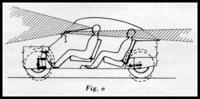
The edges of the roof have a marked downward curve and are provided with reinforcements.
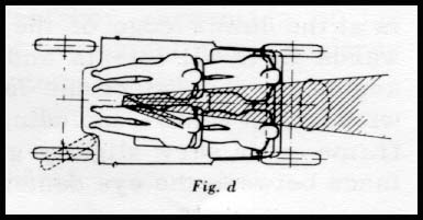
The sides of the floor are strengthened by means of straight, closed plate sections. Thus, the roof and flooring extend towards the front, forming two strong beams which are fixed at the back of the shell. Between the front ends of these beams a folded front wall "the fire wall" is located in which the frame for the windshield is mounted. Each of the side posts for the wind screen contains a special tubular section which is extended forwards and downwards and is fixed in the fire wall in order to absorb the vertical and transverse forces set up. To enable it to take up vertical loads, the fire wall is provided with strong lateral side rnembers which, together with the above-mentioned tubular sections, constitute the front posts. The latter are, moreover rigidly fastened to the closed side sections of the floor.
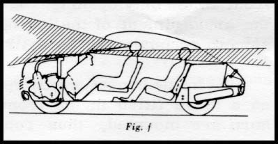
The front wheels are located immediately in front of the lower part of the fire wall. The shape of the fire wall, viewed at the center section of the car, is such that it forms with the front part of the floor a channel girder which exceeds two feet in height. The wheel housings for the two sides are fixed at a short distance from the ends of this channel girder. These also form the side walls of the engine compartment and constitute a supporting member for the front of the car together with the flooring which extends between them.
The dimensions for the materials forthe various parts described above are chosen in such a way that all of the parts cooperatein the most effective manner,that is to say, they all approach approximately the same percentage of the maximum permissible stresses, with due regard to the shape of the parts at the maximum loads occurring. It has been possible to verify this by loading tests carried out under realistic conditions, in which the stresses in the construction were measured by means of strain gauges in the same manner as that adopted for the load testing of aircraft. Deformation measurements showed that a very rigid construction has been achieved, notwithstanding the fact that closed sections are included only in the floor edges, the windshield posts and the rear spring support.
The body, which serves simultaneously as the framework, may be regarded as a closed shell which combines the tasks of supporting the passengers and protecting them against adverse atmospheric conditions and shocks (in case of accidents) whilst at the same time it provides the necessary stiffening and load-supporting connection between the four wheels.
From the p6int of view of strength the shell is somewhat incomplete on account of the openings for the glass windows and doors which carry no load. The door openings and windows present the most serious problems. With the reinforcements that have been introduced, however, the body functions approximately as a rigid shell in the manner described below.
The rear window is surrounded by a frame fixed on the inside by spot-welding so that it causes no appreciable weakening of the structure. The rear sidewindows are substantially triangular in shape and, in consequence of the stiffening frames employed, may be regarded as entirely rigid.
It will be seen, therefore, that we may consider the shell as a continuous unit from the back up to the rear edge of the doors. This part of the body resembles an egg shell of which a large part of one end has been removed. Consequently, the edge of the shell can be easily deformed, but by inserting a bulkhead or bottom a short distanceinside the shell a great stiffening effect is produced. In the body this bulkhead consists of the sloping wall which serves simultaneously as the back support for the rear seats. (It is true that there is a large aperture in the wall to allow access to the luggage compartment,but owing to the wide surface of the plates on three sides this wall functions as a solid wall.)
That part of the body described hitherto represents a rear closed portion in which the roof is rigidly fixed at the bottom and the outer panelling of the body to the sides.
The edges of the roof have a marked downward curve and are provided with reinforcements.
The sides of the floor are strengthened by means of straight, closed plate sections. Thus, the roof and flooring extend towards the front, forming two strong beams which are fixed at the back of the shell. Between the front ends of these beams a folded front wall "the fire wall" is located in which the frame for the windshield is mounted. Each of the side posts for the wind screen contains a special tubular section which is extended forwards and downwards and is fixed in the fire wall in order to absorb the vertical and transverse forces set up. To enable it to take up vertical loads, the fire wall is provided with strong lateral side rnembers which, together with the above-mentioned tubular sections, constitute the front posts. The latter are, moreover rigidly fastened to the closed side sections of the floor.
The front wheels are located immediately in front of the lower part of the fire wall. The shape of the fire wall, viewed at the center section of the car, is such that it forms with the front part of the floor a channel girder which exceeds two feet in height. The wheel housings for the two sides are fixed at a short distance from the ends of this channel girder. These also form the side walls of the engine compartment and constitute a supporting member for the front of the car together with the flooring which extends between them.
The dimensions for the materials forthe various parts described above are chosen in such a way that all of the parts cooperatein the most effective manner,that is to say, they all approach approximately the same percentage of the maximum permissible stresses, with due regard to the shape of the parts at the maximum loads occurring. It has been possible to verify this by loading tests carried out under realistic conditions, in which the stresses in the construction were measured by means of strain gauges in the same manner as that adopted for the load testing of aircraft. Deformation measurements showed that a very rigid construction has been achieved, notwithstanding the fact that closed sections are included only in the floor edges, the windshield posts and the rear spring support.
 The crankshaft is straightforward and rugged in design. It consists of six identical disks interconnected by main and big-end bearing pins. All constituent parts are case or induction-hardened. The crankshaft is carried in four similar SKF single-row ball bearings which all satisfy stringent requirements on radial play and tolerances on outside and inside diameters. All main bearing seats are made to tolerances as close as 0. 019 mm. - another example of the high precision built into this engine.
The use of crankcase compression to scavenge the engine requires efficient sealing between the crankcases of the three cylinders. This is ensured by labyrinth seals consisting of ordinary piston rings fitted in their grooves with small clearance and pressing onwards. The distributor drive is sealed off by spring loaded rubber seals. The three big-end bearings are designed as double-Pow cylindrical roller bearings with the rollers directly contacting the hardened surfaces of the big-end pins and connecting rods. The roller cages are die cast in one piece. The simple construction of the crankshaft, the direct journalling of the main bearings in the cast-iron seats and the direct contact of the big-end bearing rollers with the big-end pins and connecting rods have kept the number of tolerances to a minimum. This in turn has made it possible to keep all bearing play within the narrow limits required for quiet running without having to resort to a comprehensive selection system.
The ignition system is of conventional automobile type with 12-volt primary voltage, differing only in that distributor r. p.m. is the same as crankshaft r. p.m., which is not the case in 4-stroke engines.
The cooling system includes fan, thermostat and a circulating pump with rotor attached to the extended generator shaft. Generator and fan are driven by a common V-belt. The radiator is positioned immediately behind and higher than the engine so that the fan forces air through it. Cooling-system capacity is sufficient for continuous city driving in the hottest weather and has also proved satisfactory for driving over the steepest alpine passes. Our decision to use water cooling instead of air cooling was greatly influenced by the wish to provide a really effective heating system for the car; with water cooling the heat can be carried in small size hoses from the heat-producing engine to the most suitable point for warming up the ventilation air. In direct aircooling system, the air has to flow over engine parts which are often dirty, oily, etc. ; the ventilation air is also liable to pollution from defective gaskets and similar.
Quick heating-up of the coolant is assisted by a thermostat which shuts off the flow of water to the radiator during the warming up period and directs the entire quantity through the heat exchanger for ventilation air. The heat exchanger is situated forward of the instrument panel and immediately in front of and under the fresh-aii- intake at the lower edge of the windshield. Fresh air thus has onlya short distance to pass through the heat exchanger and into the car.
The fuel system consists of fuel tank (situated a littlebehind the rear seat) fuel linewith electromagnetic fuel pump, electric fuel gauge with optical warning when tank content has fallen to approximately two gallons and carburetor of down-dratight type.
Theinlet and exhaust systems play an important part in theoutput of a two-stroke engine and its function in general. They have been developed in extensive and intimate cooperationwith firms specializingin the field. The induction silencer contains an air filter. A preheater for the induction air prevents the formation of ice in the carburetor in damp weather and at tempera tures below 601 F. This may well be removed in summertime to achieve a slight increase in engine output.
POWER TRANSMISSION
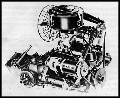
The engine is mounted longitudinally forward of the front axle. Power is transmitted through a single dry disk clutch and via a free wheel to the gearbox behind the front axle. A pinion shaft from the gearbox drives the ring gear, and articulated shafts from each side of the differential drive the front wheels.
The crankshaft is straightforward and rugged in design. It consists of six identical disks interconnected by main and big-end bearing pins. All constituent parts are case or induction-hardened. The crankshaft is carried in four similar SKF single-row ball bearings which all satisfy stringent requirements on radial play and tolerances on outside and inside diameters. All main bearing seats are made to tolerances as close as 0. 019 mm. - another example of the high precision built into this engine.
The use of crankcase compression to scavenge the engine requires efficient sealing between the crankcases of the three cylinders. This is ensured by labyrinth seals consisting of ordinary piston rings fitted in their grooves with small clearance and pressing onwards. The distributor drive is sealed off by spring loaded rubber seals. The three big-end bearings are designed as double-Pow cylindrical roller bearings with the rollers directly contacting the hardened surfaces of the big-end pins and connecting rods. The roller cages are die cast in one piece. The simple construction of the crankshaft, the direct journalling of the main bearings in the cast-iron seats and the direct contact of the big-end bearing rollers with the big-end pins and connecting rods have kept the number of tolerances to a minimum. This in turn has made it possible to keep all bearing play within the narrow limits required for quiet running without having to resort to a comprehensive selection system.
The ignition system is of conventional automobile type with 12-volt primary voltage, differing only in that distributor r. p.m. is the same as crankshaft r. p.m., which is not the case in 4-stroke engines.
The cooling system includes fan, thermostat and a circulating pump with rotor attached to the extended generator shaft. Generator and fan are driven by a common V-belt. The radiator is positioned immediately behind and higher than the engine so that the fan forces air through it. Cooling-system capacity is sufficient for continuous city driving in the hottest weather and has also proved satisfactory for driving over the steepest alpine passes. Our decision to use water cooling instead of air cooling was greatly influenced by the wish to provide a really effective heating system for the car; with water cooling the heat can be carried in small size hoses from the heat-producing engine to the most suitable point for warming up the ventilation air. In direct aircooling system, the air has to flow over engine parts which are often dirty, oily, etc. ; the ventilation air is also liable to pollution from defective gaskets and similar.
Quick heating-up of the coolant is assisted by a thermostat which shuts off the flow of water to the radiator during the warming up period and directs the entire quantity through the heat exchanger for ventilation air. The heat exchanger is situated forward of the instrument panel and immediately in front of and under the fresh-aii- intake at the lower edge of the windshield. Fresh air thus has onlya short distance to pass through the heat exchanger and into the car.
The fuel system consists of fuel tank (situated a littlebehind the rear seat) fuel linewith electromagnetic fuel pump, electric fuel gauge with optical warning when tank content has fallen to approximately two gallons and carburetor of down-dratight type.
Theinlet and exhaust systems play an important part in theoutput of a two-stroke engine and its function in general. They have been developed in extensive and intimate cooperationwith firms specializingin the field. The induction silencer contains an air filter. A preheater for the induction air prevents the formation of ice in the carburetor in damp weather and at tempera tures below 601 F. This may well be removed in summertime to achieve a slight increase in engine output.
POWER TRANSMISSION
The engine is mounted longitudinally forward of the front axle. Power is transmitted through a single dry disk clutch and via a free wheel to the gearbox behind the front axle. A pinion shaft from the gearbox drives the ring gear, and articulated shafts from each side of the differential drive the front wheels.
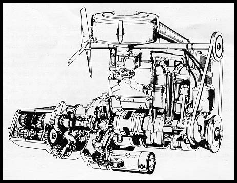 The construction of a gearbox sufficiently short for the available space was a major design problem. The space behind the front axle is not substantially greater than in the SAAB 92 where, however, the gearbox is forward of the front axle. A short gearbox has been obtained by transmitting the power to the pinion shaft by gears direct from the drive shaft from the engine (2nd and 3rd speeds) and via a third shaft, which is used both for Ist speed and reverse. Length has been kept to a minimum in all cases by transferring power to only two gears on the pinion shaft: the forward gear being used for driving on both Ist and 3rd, the rear for both 2nd and reverse. It is now easy to change down from 3rd to 2nd and from 2nd to lst without declutching, a great help when driving in heavy traffic. lst is engaged by a dog clutch with large clearance. Only reverse is sliding-gear engaged.
The power unit is mounted on two rubber cushions on the front end of the engine and one behind the gearbox. The front pair are of block type and the rear cushion is circular. This mounting allows the unit to oscillate around the very axis it would choose if it were suspended infinitely unrestricted while the engine was idling. The front silencer is included in the weight of the unit and this helps lower the frequency and the front end of the above-mentioned axis of oscillation. All this ensures smooth idling.
PERFORMANCE
The remarkable capacity of this type of engine for high r. p.m. and high loading without greater over-heating or wear of parts than are occasioned by low r. p. m. and loading permits continuous driving on open roads at speeds approaching the car's maximum. Under favorable conditions, such as slight down gradients or following winds, the endurance of the engine can be utilized to drive at speeds considerably in excess of the car's maximum level-ground, still-air speed without danger of damage to the engine.
When overtaking, 2nd can be used up to approximately 75 km/h. (45 m. p. h.), and 3rd provides excellent acceleration around the 80-90 km/h. (50-55 m.p.h.) mark because the engine develops its maximum torque at a relatively high r. p. m. At speeds below 60 km/h. (35-40 m.p.h.) it is, however, necessary to make good use of the gears if the available power is to be utilized to the full.
WHEELS AND SUSPENSION
The disktype wheels have 4-in. rims for good lateral rigidity. The 5. 00" x 15" tires are of tubeless type. Front wheel suspension is of new type with the stub axle carried in a single angular contact ball bearing. Extensive tests have given entirelysatisfactory function and life.
The construction of a gearbox sufficiently short for the available space was a major design problem. The space behind the front axle is not substantially greater than in the SAAB 92 where, however, the gearbox is forward of the front axle. A short gearbox has been obtained by transmitting the power to the pinion shaft by gears direct from the drive shaft from the engine (2nd and 3rd speeds) and via a third shaft, which is used both for Ist speed and reverse. Length has been kept to a minimum in all cases by transferring power to only two gears on the pinion shaft: the forward gear being used for driving on both Ist and 3rd, the rear for both 2nd and reverse. It is now easy to change down from 3rd to 2nd and from 2nd to lst without declutching, a great help when driving in heavy traffic. lst is engaged by a dog clutch with large clearance. Only reverse is sliding-gear engaged.
The power unit is mounted on two rubber cushions on the front end of the engine and one behind the gearbox. The front pair are of block type and the rear cushion is circular. This mounting allows the unit to oscillate around the very axis it would choose if it were suspended infinitely unrestricted while the engine was idling. The front silencer is included in the weight of the unit and this helps lower the frequency and the front end of the above-mentioned axis of oscillation. All this ensures smooth idling.
PERFORMANCE
The remarkable capacity of this type of engine for high r. p.m. and high loading without greater over-heating or wear of parts than are occasioned by low r. p. m. and loading permits continuous driving on open roads at speeds approaching the car's maximum. Under favorable conditions, such as slight down gradients or following winds, the endurance of the engine can be utilized to drive at speeds considerably in excess of the car's maximum level-ground, still-air speed without danger of damage to the engine.
When overtaking, 2nd can be used up to approximately 75 km/h. (45 m. p. h.), and 3rd provides excellent acceleration around the 80-90 km/h. (50-55 m.p.h.) mark because the engine develops its maximum torque at a relatively high r. p. m. At speeds below 60 km/h. (35-40 m.p.h.) it is, however, necessary to make good use of the gears if the available power is to be utilized to the full.
WHEELS AND SUSPENSION
The disktype wheels have 4-in. rims for good lateral rigidity. The 5. 00" x 15" tires are of tubeless type. Front wheel suspension is of new type with the stub axle carried in a single angular contact ball bearing. Extensive tests have given entirelysatisfactory function and life.
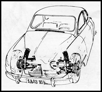 The rubber bearings are of the type where angular movements take place without any sliding motion whatever. All the relative movement is absorbed elastically by shear in the rubber. The roll center lies somewhat above the ground level. The coil spring is on top of the upper suspension arm. A stabilizer (anti-roll bar) connects the two lower suspension arms and the outer ends of the arms are connected to the steering knuckle housing by ball and socket joints. Ball and socket joints are becoming increasingly popular for such purposes, not least in the U.S.A. To obtain hardened surfaces without loss of the necessary toughness in neighboring areas of the parts, good use is made of the induction hardening process that is so successfully replacing case hardening.
TheU-sectioned rigid axleof therearsuspension system is joined to the bodyby aresilient bearing in the car's plane of symmetry and by two longitudinal links at the sides. The central bearing is designed to take up lateral forces and, together with the springs, the braking torque. The side links keep the rear axle at right angles to the longitudinal axis of the car and carry over the braking forces from the rear wheels. The coil springs are located close to the wheels on the inside and when they function without roll compress an amount equal to the vertical movement of the wheel relative to the body. When the spring system functions without roll, shock absorber movement is approximately half that of the wheels. When roll does occur however, shock absorber movement is considerably greater, approximately 80% of wheel movement. The roll center of the rear end of the car is determined by the central bearing position. This has been placed just above floor level, which is a normal or perhaps rather lower position than usual. In addition to the above shock-absorber characteristics, the rear axle design offers the following distinctive advantages:
The rubber bearings are of the type where angular movements take place without any sliding motion whatever. All the relative movement is absorbed elastically by shear in the rubber. The roll center lies somewhat above the ground level. The coil spring is on top of the upper suspension arm. A stabilizer (anti-roll bar) connects the two lower suspension arms and the outer ends of the arms are connected to the steering knuckle housing by ball and socket joints. Ball and socket joints are becoming increasingly popular for such purposes, not least in the U.S.A. To obtain hardened surfaces without loss of the necessary toughness in neighboring areas of the parts, good use is made of the induction hardening process that is so successfully replacing case hardening.
TheU-sectioned rigid axleof therearsuspension system is joined to the bodyby aresilient bearing in the car's plane of symmetry and by two longitudinal links at the sides. The central bearing is designed to take up lateral forces and, together with the springs, the braking torque. The side links keep the rear axle at right angles to the longitudinal axis of the car and carry over the braking forces from the rear wheels. The coil springs are located close to the wheels on the inside and when they function without roll compress an amount equal to the vertical movement of the wheel relative to the body. When the spring system functions without roll, shock absorber movement is approximately half that of the wheels. When roll does occur however, shock absorber movement is considerably greater, approximately 80% of wheel movement. The roll center of the rear end of the car is determined by the central bearing position. This has been placed just above floor level, which is a normal or perhaps rather lower position than usual. In addition to the above shock-absorber characteristics, the rear axle design offers the following distinctive advantages:
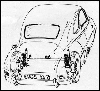 No rear-end lift when braking; brake torque produces spring compression which compensates for the rear-end lift that usually accompanies violent braking. The car remains horizontal.
No swaying in S-bends; the shock absorbers react to abrupt swerves, dampening sway and stabilizing, to great advantage of the steering properties.
Small space requirements; since the central portion of the 'axle does not move vertically, a maximum of space is available for luggage, etc.
The changeover from torsion bars to coil springs is characteristic of the development work that SAAB has carried out on the new car. Spring action is only slightly influenced by the type of spring chosen, in as far as the design is such that the unsprung weight is not increased excessively. In the front spring system of the SAAB 93 the coil springs account for only about 5@o of the unsprung weight. The advanced manufacturing methods used permit the low-cost production of high-stress springs of this type without sacrifice of reliability.
An obvious advantage of a rigid rear axle is that the rearwheels are always at right angles to the ground even if the car does lean. The front wheels, on the other hand, move essentially parallel with the car's plane of symmetry. In the case of abrupt steering movements this has an understeering tendency,because the sideslip for wheels that are at right angles to the ground (rear) is less than for wheels (front) that incline outwards when cornering. The rods of the rack and piriion steering are designed as extensions from the rack ends. Extensive tests were made to obtain the best possible geometry; the steering knuckle line, for instance, was chosen to eliminate completely self-rotation of the steering wheel under all circumstances (this disadvantage is otherwise quite common).
With two people in the car theweight distribution is approximately 58% on the front wheels and 42% on the rear wheels. This weight distribution ensures good driving wheel adhesion. It keeps the load on the front wheels greater than that on the rear wheels as long as the up gradient does not exceed 25%.
When turning round, driving out of garages, etc., the front end will travel further than the rear end; this results in greater traction for the car as a whole than the front wheels alone can produce. The weight distribution is also favorable for driving in side winds.
STEERING PROPERTIES
SAAB 93 is "consistently under-steered" except when the hand brake alone is used, as this acts on the rear wheels. Under all other conditions -when braking on slippery roads, when the steering wheel is turned too violently, when accelerating excessively, and in acute S-bends - the car always tends to travel on a straighter path than it would for the same front wheel angle at creep speeds. Hard-to-manage tail swishing is thereby avoided and it is easy to regain control of the car if it skids unintentionally. According to one school of thought, a car is more maneuverable if the rear wheels can be made to skid easily. Direction of travel can then be changed quickly when required. This may be true for driving aces but there is no doubt that a car for the general public should be under-steered, i.e., the car should have directional stability.
TESTING
Development work on the SAAB 93 has included extensive preliminary tests designed to reveal any weak points in the construction, as well as wear phenomena, elasticity, etc.
The accumulated experience of years with the SAAB 92 was utilized in these tests to determine loads, working conditions, etc. , very accurately. Tests on parts included torsional fatigue tests on the stabilizer and on coil springs and dynamic load tests on the front spring arms. As soon as a number of test cars were ready, some of them were put through alternating road tests and special tests, the latter including thousands of circuits at full speed in both directions round a small circular track with an uneven surface, consisting of radially arranged planks. Runs were also made over a special track about 100 yards long, where 4-in. high blocks arranged in zig-zag subject the wheel suspension, spring system, shock absorbers, steering gear and body to loads which would normallyoccur onlyif the car ran off the road, drove over deep pot holes, or the like. No part was approved before it could stand up to 1000 runs overthe "steps" and 200 jun,ps from the "jumping board ". We are therefore introducing the SAAB 93 -the first radically new model in the company's history with every confidence in its durability and all-round dependability.
SPECIFICATIONS
No rear-end lift when braking; brake torque produces spring compression which compensates for the rear-end lift that usually accompanies violent braking. The car remains horizontal.
No swaying in S-bends; the shock absorbers react to abrupt swerves, dampening sway and stabilizing, to great advantage of the steering properties.
Small space requirements; since the central portion of the 'axle does not move vertically, a maximum of space is available for luggage, etc.
The changeover from torsion bars to coil springs is characteristic of the development work that SAAB has carried out on the new car. Spring action is only slightly influenced by the type of spring chosen, in as far as the design is such that the unsprung weight is not increased excessively. In the front spring system of the SAAB 93 the coil springs account for only about 5@o of the unsprung weight. The advanced manufacturing methods used permit the low-cost production of high-stress springs of this type without sacrifice of reliability.
An obvious advantage of a rigid rear axle is that the rearwheels are always at right angles to the ground even if the car does lean. The front wheels, on the other hand, move essentially parallel with the car's plane of symmetry. In the case of abrupt steering movements this has an understeering tendency,because the sideslip for wheels that are at right angles to the ground (rear) is less than for wheels (front) that incline outwards when cornering. The rods of the rack and piriion steering are designed as extensions from the rack ends. Extensive tests were made to obtain the best possible geometry; the steering knuckle line, for instance, was chosen to eliminate completely self-rotation of the steering wheel under all circumstances (this disadvantage is otherwise quite common).
With two people in the car theweight distribution is approximately 58% on the front wheels and 42% on the rear wheels. This weight distribution ensures good driving wheel adhesion. It keeps the load on the front wheels greater than that on the rear wheels as long as the up gradient does not exceed 25%.
When turning round, driving out of garages, etc., the front end will travel further than the rear end; this results in greater traction for the car as a whole than the front wheels alone can produce. The weight distribution is also favorable for driving in side winds.
STEERING PROPERTIES
SAAB 93 is "consistently under-steered" except when the hand brake alone is used, as this acts on the rear wheels. Under all other conditions -when braking on slippery roads, when the steering wheel is turned too violently, when accelerating excessively, and in acute S-bends - the car always tends to travel on a straighter path than it would for the same front wheel angle at creep speeds. Hard-to-manage tail swishing is thereby avoided and it is easy to regain control of the car if it skids unintentionally. According to one school of thought, a car is more maneuverable if the rear wheels can be made to skid easily. Direction of travel can then be changed quickly when required. This may be true for driving aces but there is no doubt that a car for the general public should be under-steered, i.e., the car should have directional stability.
TESTING
Development work on the SAAB 93 has included extensive preliminary tests designed to reveal any weak points in the construction, as well as wear phenomena, elasticity, etc.
The accumulated experience of years with the SAAB 92 was utilized in these tests to determine loads, working conditions, etc. , very accurately. Tests on parts included torsional fatigue tests on the stabilizer and on coil springs and dynamic load tests on the front spring arms. As soon as a number of test cars were ready, some of them were put through alternating road tests and special tests, the latter including thousands of circuits at full speed in both directions round a small circular track with an uneven surface, consisting of radially arranged planks. Runs were also made over a special track about 100 yards long, where 4-in. high blocks arranged in zig-zag subject the wheel suspension, spring system, shock absorbers, steering gear and body to loads which would normallyoccur onlyif the car ran off the road, drove over deep pot holes, or the like. No part was approved before it could stand up to 1000 runs overthe "steps" and 200 jun,ps from the "jumping board ". We are therefore introducing the SAAB 93 -the first radically new model in the company's history with every confidence in its durability and all-round dependability.
SPECIFICATIONS